Check the electrical circuit diagram online. How to draw a diagram online? Characteristic features of the system
To design and test simple circuits, just take a breadboard and start placing components of interest on it with the ability to quickly replace one or another element. Breadboards make it easy to check the circuit for errors before soldering the finished product. But if you have a more complex circuit, or if you need to run some rather complex signal flow simulations on your project before you start building the final device, you will need circuit simulation software or simply a simulator.
The main requirements that most people (especially newbies to electronics) have for circuit simulators are ease of use and as low a price as possible, ideally for free. Functionality is also very important.
While it's easy to get a trial version of something like OrCAD PSpice, this software doesn't have all the features available unless you're willing to fork out to get them, of course. Luckily, there is a completely free full-featured electronic circuit simulation software called Qucs (Quite Universal Circuit Simulator) released under the GPL license. Qucs offers a worthy alternative to other paid circuit simulators. Qucs runs its own software separately from SPICE because SPICE is not licensed for re-use.
Qucs has most of the components you'll need for near-professional modeling, and the software also has a huge number of different transistor models. The program itself can be found at http://qucs.sourceforge.net/. For more information, the Qucs Wikipedia page (https://en.wikipedia.org/wiki/Quite_Universal_Circuit_Simulator) lists all the available features and also has a FAQ page.
According to the developers, Qucs is not yet completely finished, and, most likely, functions will be added from time to time, so there may not be a final version, however, today Qucs is already a very functional tool for modeling electronic circuits. The Qucs graphical user interface is well developed and allows you to set up circuits and present simulation results in various diagram types. The screenshots below confirm this.


Today I want to tell you about a very interesting service that I came across on the Internet - this is service for drawing electrical circuits called Scheme-it. I liked the service because it allows you to draw an electrical circuit "on the knee", that is, quickly. Below I have prepared a brief overview of this service.
Scheme-it is an online tool for drawing schematic and structural diagrams, electrical drawings, which allows you to not only create diagrams, but also save them on the server to give open web links to your diagrams.
The service is available at http://www.digikey.com/schemeit.
The service includes a complete set of schematic symbols for building electrical circuits, as well as an integrated Digi-Key catalog that supports the insertion of product images and photos.
The tool also includes an integrated list of elements (specification), with which you can select a specific electrical and radio element from the catalog and associate the parameters of a real element with a circuit element.
How to save, open and delete wiring diagrams in Scheme-it.
In order to save electrical diagrams created in the program and subsequently open them from the Digi-Key server, you need to log in to the site using your login.
If you do not have a Digi-Key account, then go through a simple registration procedure on the site through the window that opens when you enter the Digi-Key site on the page of the online diagram drawing program at http://www.digikey.com/schemeit.

Or click on the Login / Register button (in the upper right corner of the application) and create a new account.
![]()
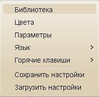
Main menu of the program (Main)
The main menu consists of four blocks: Project, Output, Edit, History.
The "New" button creates a new project. If you have a project open with unsaved changes, the application will prompt you to save your changes before creating a new project.
The "Open" button shows a dialog box containing previously saved projects. The dialog box also contains a delete button that allows you to delete the project. Highlight the project you want to delete and then click on the button Delete.
All of the above functions will be available to you after registering on the program website.
Output block.
The "Export" button allows you to export the current project as a *.png image file or as a pdf document.
The "Share" button allows you to create and share a web link of your schema. A web link contains a schematic image file within a web page and is viewable in a standard web browser. The link is open.
The "Print" button opens the diagram in a new window, which can be printed using the standard browser menu.
Edit block.
The "Cut" button cuts the selected circuit element to the clipboard.
Button "Copy" - places the selected item on the clipboard.
The Paste button retrieves the previously copied element from the clipboard.
The "Delete" button removes the selected element from the scheme.
History block
The Back button takes you back one action.
Button "Forward" transition to a previously performed operation.
Drawing diagrams with Scheme-it.
On the left side of the site, Scheme-it contains an extensive library of schematic and graphic symbols (UGOs) for use in circuit and structural electrical diagrams, as well as in various drawings. To place these symbols on the diagram, click on the desired category, select the symbol family, then click on the symbol and drag it onto the diagram (using the left mouse button).

Thus, by sequentially moving the necessary elements, and connecting them together, an electrical circuit is created.
To connect the outputs of the elements to each other, left-click on the selected output of the radio element and, without releasing the mouse, drag a line to the next element.

An example of drawing an electrical circuit of an amplifier on transistors.

There is a tab to change the spatial orientation of objects on the electrical diagram. By clicking on this tab, the following tools will become available to you:

Creation of custom conditional-graphic displays and symbols of elements of eclectic schemes
Scheme-it has the ability to create your own symbols. Category "Custom character"(Custom Symbol) has the simplest elements to create your own symbols.

The simplest elements include the body of the element and the leads of the element (legs, contacts, etc.).
Schematic element body.
The case is needed to create the basis for the future conditional graphic element of the circuit. Body shapes include: rectangle, rounded rectangle and triangle. When you move a body onto a schematic, the element is automatically included in the schematic specification.
Element pins.
With the help of the conclusions, the final appearance of the graphic element is created. The outputs can be connected from above, below, left, right.
To connect the corresponding output, simply drag it to the future circuit.
The pins can be moved along the corresponding side.
Connection of electrical circuit elements.
Scheme-it allows you to create connections of three types:
Output-output (contact-contact);
Output-wire:
Wire-wire.
Connection type: "Output-output (contact-contact)"

To connect two outputs of radioelements, it is necessary to left-click on the first output, move the cursor to the second output and click the left mouse button. To change the configuration of the connecting wire, click on it with the mouse and drag it to the desired location.
Connection type "Conclusion-wire".

To connect the output of a circuit element with a wire, you need to click on the output of the element with the left button, move the cursor to the required connection point on the wire and click the left button a second time.
Connection type "Wire - wire".

To connect two wires, you need to click on the selected connection point of the first wire, thereby creating the first connection, then clicking on the desired location on the second wire will create the second connection.
Adding and editing the text of circuit elements.
Text properties.
When adding various elements to the scheme, some text marks appear next to them, for example, designation, denomination, etc.
To change the properties of this text, select this text mark (highlighted with a green dotted ribbon), go to the top menu to the “Font” tab. Next, in the “Font” tab, the necessary text properties are set (color, font scale, style, alignment, wrapping).
Adding text to existing characters.
You can add text to an existing symbol by double-clicking the left mouse button on the element image. This will open a window "Component Properties", in which you can fill in the missing characteristics of this element.

Such as the "designation", "name", "value" etc. Do not forget to display these characteristics on the diagram, check the boxes next to them.
List of elements (BOM manager)
The online service for drawing diagrams Scheme-it has a tool - a list of elements (specification), in which all elements of the diagram with their properties are automatically added: designation, name, denomination, part number, description, etc.

When adding a new element to the scheme, the program automatically adds it to the list of elements.
To view the properties of a schema element and its attributes, double-click on the selected element, after which the element's properties window will open.
In this window, you can change any attributes of the schema element.
On the right side of the Scheme-it schematic drawing program, there is a panel with which you can search the Digi-Key catalog.

This function is useful for viewing reference data for a particular radio element.

Service advantages:
- a fairly simple program interface (despite the English language);
- service is a good opportunity to draw diagrams on someone else's computer without installing special programs (it is enough to have the Internet);
- the ability to save schemes on the server;
- publication of open links to your schemes located on the server;
- export to PNG image or PDF document;
Flaws:
- the absence of the Russian language of the interface and help (however, you can use the translator built into the browser!);
- the component library is not made according to domestic standards;
- the need to have a permanent Internet connection for the service to work.
So, having worked in the program, I can do the following conclusions:
Quite an interesting service, although the library of circuit elements is not made according to GOST, there are interesting designations and icons. I recommend using small electrical circuits for drawing, in the event that it is not possible to work with special programs for drawing circuits (for example, someone else's computer, etc.). The available library is sufficient for drawing basic electronics circuits.
P.S: The option of using the service for drawing electrical circuits Scheme-it using the translator built into the browser

I propose to watch a detailed video on how to use the online service for drawing electrical circuits:
List free electronic circuit simulation programs online very helpful for you. These circuit simulators that I offer do not need to be downloaded on a computer and can be run directly from the website.1. EasyEDA electronic circuit design, circuit modeling and PCB design:
EasyEDA is amazing free online circuit simulator which is very suitable for those who love electronic circuit. The EasyEDA team has been aiming to make a sophisticated design program on a web platform for several years and now the tool is becoming great for users. The software environment allows you to design the circuit yourself. Verify the operation via circuit simulator. When you make sure the circuit function is good, you will design the PCB with the same software. There are over 70,000+ charts available in their web databases along with 15,000+ Pspice library programs. On the site you can find and use many designs and electronic circuits made by others, because they are public and open hardware. It has some pretty impressive import (and export) options. For example, you can import files into Eagle, Kikad, LTspice and Altium Designer, and export the files to .PNG or .SVG. There are many examples on the site and useful training programs that make it easy for people to manage.

2. Circuit Sims: This was one of the first web based open source circuit emulators I tested a few years ago. The developer failed to improve the quality and increase the graphical user interface.

3. DcAcLab has visual and attractive graphics but is limited to circuit simulation. This is undoubtedly a great program for learning, very easy to use. This makes you see the components as they are made. It won't let you design a circuit, but will only let you practice.

4. EveryCircuit is an online electronic emulator with nice graphics. When you enter the online program and it will ask you to create a free account so you can save your designs and have a limited area to draw your diagram. To use it without restrictions, it requires an annual fee of $10. It can be downloaded and used on the Android and iTunes platforms. Components have limited ability to simulate with small minimum parameters. Very easy to use, it has an excellent electronic design system. It allows you to include (embed) simulations in your web pages.

5. DoCircuits: While it leaves people confused about the site, it gives many examples of how the program works, you can see yourself in the "will start in five minutes" video. Measurements of electronic circuit parameters will be demonstrated with realistic virtual instruments.

6. PartSim electronic circuit simulator online. He was good at modeling. You can draw electrical circuits and test them. It's still a new simulator, so there are several components to make simulations to choose from.

7. 123D Circuits An active program developed by AutoDesk, it allows you to create a circuit, you can see it on a breadboard, use the Arduino platform, simulate an electronic circuit, and finally create a PCB. The components will be shown in 3D in their actual form. You can program the Arduino directly from this simulation program, (it) is really impressive.
EDA (Electronic Design Automation) - software for the development and testing of electronic equipment. In the most general sense, Sprint Layout, so common in the Russian-speaking environment, can be attributed to EDA. Better known (and more complete) products include Eagle, DipTrace, and Proteus. But they all have one small drawback - they are paid. Someone may object: the same Eagle, they say, also has a free version, albeit somewhat limited. However, these limitations sometimes become annoying rather than annoying, such as the inability to place elements outside the board, which makes it difficult to redistribute already located parts. Therefore, let's talk about KiCad - until recently a little-known, and now gaining popularity software, somewhat burdened with cross-platform, but at the same time actively developing (the current stable version was released in October 2014). In a couple of articles I will try to talk about the basic techniques and pitfalls of working with KiСad. As an example, let's take a simple Step-Up converter circuit for.
Overview of KiCad
The main window of KiCad is conditionally divided into several blocks.
- The main menu where you can create or open a project, zip it or unpack it, specify a text editor for viewing files (for example, a list of elements) and an application for viewing PDF, select a language (currently there are 19 languages in the list, including Russian), read the help and copy to the clipboard the full information about the installed version.
- The second block contains (from left to right): creation of a new project; creating a project from a template (templates, however, are not yet available, but you can create them yourself; such templates will be added to the "Custom" list); opening an existing project; saving all files, whether it is a circuit diagram or a printed circuit board; archiving the current project in zip; updating the list of project files.
- The third block contains the actual list of files - everything that has a name corresponding to the name of the project is displayed here.
- The buttons of the fourth block allow you to navigate between the following editors: Eeschema - editor of electrical circuits of the device; CvPcb - comparison of the seats of the components (in other words, the choice of the body of a particular part); Pcbnew - PCB editor; Gerbview - Gerber file viewer; Bitmap2Component - used to create logo images or to create components from existing images. Calculator - contains usefulness such as stabilizer calculator, tables of recommended track thicknesses for printed circuit boards, tables of color marking resistors, etc.
- Finally, the last block displays the actions we are doing with the current project (what was opened, what was saved, etc.).
The creation of any device begins with the creation of a new project. Therefore, click on the button Start a new project».

Select the folder of the future project, write its name, click " Save”, regardless of the style of my windows, in Windows they will be familiar and familiar.

The name of the project will appear in the left column and we can finally click on the button Eeschema. An editor like this will open...

And KiCad will gladly inform us about the absence of a certain file. It's okay, it's just a reminder that we haven't saved the schema yet, so a blank slate has been created. In general, the intricacies of the KiCad logic are sometimes amazing. Even more amusing is that this miracle is supported not by anyone, but by CERN themselves.
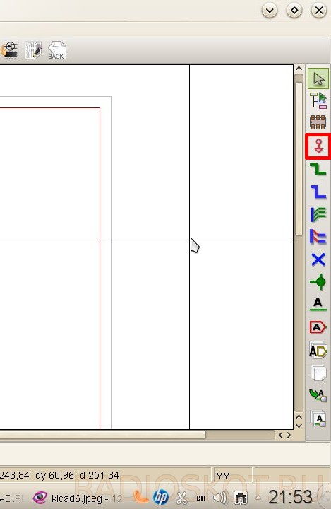
But we digress, we press OK. In the window that opens, we see the sheet on which our future scheme will be located. In fact, it can also be located outside this sheet, but these parts simply will not be printed. Around the workspace we see a bunch of different buttons, it makes no sense to explain the purpose of each of them, because on each of them a hint pops up when you hover (naturally, in Russian). It is worth mentioning only the main ones:

Don't worry, it's not as difficult as it seems at first. As a circuit, as mentioned above, I chose a converter on the MCP34063, aka MC34063. The diagram is taken from the datasheet:

First of all, let's look at the menu item " Settings”, where, in addition to color settings, appearance parameters (grid spacing, connection thickness, etc.), we are interested in the item “ Library". Libraries in KiCad, like those in Eagle, contain the components used to build the circuit. Make sure that the files supplied with KiCad are included and present in the list.

Other libraries are easily googled and added via the " Add(which is quite logical). I also recommend downloading component libraries converted from Eagle. However, you should not include all the files at once - this can lead not only to a slowdown in loading the project, but also to annoying messages about duplicating components in libraries. Having dealt with the little things, click on the button " Place a Component” in the right panel (or the item “ Component" on the menu " Post”) and click anywhere on the sheet.


In the window that appears, write in the "Name" field: 34063 - here, unlike Eagle, you do not need to know the exact name of the component, just a part of it is enough.

You can also select a component from the list (button « List of all”) or by selecting the appropriate character (“ View selection"). Click OK. If the entered designation is found in several components, we are prompted to select the desired one.

We place the symbol on the sheet.

Attention, rake! KiCad has inherited the good tradition of hotkeys from Unix systems. To move a positioned component, it is not enough just to click on it. Place the cursor on the component and press the Latin [M] (from English Move) on the keyboard, or right-click on the component and select the appropriate item in the context menu. In the same way, rotate with the [R] key and drag (i.e., move without breaking away from the chains) with the [G] key. Through the combination we add the component, and through the conductor. All the same can be done through the context menu. Hotkeys may seem awkward, but in fact, most of them are intuitive for a user familiar with English words. In addition, remembering a couple of dozen combinations, you can significantly speed up the work. So do not be lazy and read the certificate, since it is fully translated into Russian.
Following the microcircuit, we add the rest of the components to the sheet. To add passive elements, it is enough to write their more or less generally accepted designations (R, C, CP, etc.) in the "Name" field. Components once selected remain in the "History List" field for quick addition.

To complete the addition of components, press the key or select the item " Set aside the tool". To connect circuits, use " Place Explorer».

It turns out something like this:

If the connection of conductors seems inconvenient (or if the circuit is divided into separate blocks), then it makes sense to apply labels. They link separate sections of the chain, just like the names in Eagle. There are several types of labels in KiCad (local, global and hierarchical). Global and hierarchical are used in the case when the blocks of the scheme are located on several sheets and they need to be linked to each other. The most primitive is enough for us, so we choose " Place chain name(local label)".

Click the mouse on the desired connection and write the name of the label. At the same time, we choose the orientation of the label - where its connecting point will be located.

Attention, rake! KiCad does not tie the label to the connection tightly, as Eagle does. Once created, the label can be moved like any other component, however, for it to be "picked up" by the net, its connection point must match the connection on the net or component.

Having placed the necessary labels, we get the following picture:

Now let's add ground and power circuits. They refer to the instrument Host power port»
We write in the search bar " GND».

Or select the desired component through the button " List of all»

Having placed the ground, we do the same with Vin, selecting the appropriate component. It will have to be connected to a separate conductor. To do this, we take the tool " Place Explorer”, click on the desired section of the circuit and drag the conductor to the side. In order to end it not at the connection point, but at an arbitrary place on the sheet, double-click the mouse.

We place the power supply of our circuit. At the output, it is enough just to place a label like " vout».

Now let's designate the components and indicate their denominations. This is done quite simply: you need to hover over the component and press the [ V] to assign the denomination and the [ U] to indicate the sequence number. However, numbers can be assigned automatically. To do this, press the button " Label the components on the diagram»

In the window that appears, configure the designation parameters (you can leave it as is). If parts of the components have already been assigned serial numbers, then you can either continue the current numbering or start it again by first pressing the button « Reset designations».

Having finished with the preparation, click "Design components" and agree with the proposal to give everything serial numbers. Let's set the values. Move the cursor, press [ V]. If more than one component has focus, KiCad displays a small menu asking you to specify which component we want to edit.


Finally, check the correctness of the scheme by clicking the " Perform check...»

In the window that appears, you can configure the verification parameters - the rules for connections between outputs (what is considered an error, what is a warning) on the "Parameters" tab.

On the "ERC" tab, click " ERC test"... and see error messages.

At the same time, green arrows-markers will appear on the diagram next to the problem areas. Selecting a line from the list of errors in the ERC box will take us to the corresponding marker. So what is our problem? And here's the thing: KiCad is not enough to just put a power port on the circuit, you also need to indicate that the power port added through the power port is exactly the power port, and not something else. The apotheosis of crutches, in my opinion, but completely solvable. You just need to take the tool again " Host power port» and select the component in the list of ports PWR_FLAG.

The following symbol will appear on the diagram:

PWR_FLAG is displayed only on the diagram and is needed solely for successful verification of its correctness. We cling it to the plus of the power supply and the GND circuit. We run the ERC test again - there are no more errors.
Attention, rake! When microcircuits with no pins connected anywhere are used, the ERC test will swear in their direction. To prevent this from happening, all unused outputs should be flagged "Not connected".
As a result, we got the following scheme:

To print it, click on the button on the top panel " Printing a diagram", or select this item in the menu" File».

Attention, rake! Linux users may encounter a problem when a blank page is printed instead of a diagram. This is due to wxWidgets not working correctly with printers.
- a) update wxWidgets to version 3.0;
- b) export the scheme to an accessible graphic format or to a PDF file, and then print it.
It’s not entirely clear what motivated the KiCad developers, but the usual export is in the paragraph “ draw».

Here we select the format, set the color mode and image quality (the default line thickness), choose whether we need to export the sheet frame along with the scheme. Here, perhaps, is all that is enough to know to get started with EESchema. And next time we will talk about the subtleties and the creation of new components for libraries. Review by - Vetinari.
Discuss the article SOFTWARE FOR DEVELOPING AND TESTING SCHEMES
Qucs, also known as the Quite Universal Circuit Simulator, was developed as an open source, open source, open source electronic circuit and circuit simulator. The program supports all kinds of circuit simulation, such as DC, AC, S-parameters, harmonic balance analysis, noise analysis and so on. Simulation results can be viewed on the presentation page or the program window.
Qucsator, the back-end of the program, is a command-line simulator that manages a list of networks of a specific Qucs I/O format. By default, it was created to work with the Qucs project, but can be used with other applications as well. The program has support for exporting symbol images with Verilog-A files to C++ code, support for direct communication with Verilog-HDL symbols and VHDL subchains. Recent versions of Qucs have a GNU/Octave interface.
Key features and functions
- support for Verilog-HDL and Verilog-A syntax in text documents;
- support for exporting C++ code;
- support for equations for Verilog-HDL and VHDL subcircuits;
- precompiled VHDL modules and libraries;
- support for all modern components;
- open source makes it possible to develop extensions;
- customizable and extensible interface;
- built-in file converter;
- the ability to download additional interface languages.