Grandfather club detector of high-frequency fields. Simple DIY microwave field indicators
Simple scheme field indicator, which is based on the cheap, common LM358 op-amp chip, has 2 levels of LED indication. To enlarge, click on the image.
The sensitivity of the circuit is affected primarily by the antenna and diodes VD1, VD2. The following diodes are suitable: “GI401A, B; 1I401A, B; AI402, 3I402; 1I403, GI403.” Since I did not have any of the listed diodes, I had to select others based on the highest sensitivity. Germanium detector diodes “AA143” were suitable. The operating voltage of the HF indicator is 6-12V. The current consumption of the circuit is 0.4-1 mA in standby mode. The current in detection mode depends on the current consumption of the LEDs and the values of resistors R4, R5. The LEDs had to be slightly polished to diffuse the light.

The indication thresholds are set by variable resistors R2, R3. If there are no resistors R2, R3 with values as in the circuit, then they can be selected in this way: If R2, R3 ~ 1k, then R1 ~ 30k; R2,R3~5k, then R1~150k; R2,R3~10k, then R1~300k and so on, observing the ratio.

You need to adjust R2, R3 after completely soldering all components (including the antenna), cleaning the board from flux (in my case, rosin) and other contaminants, since the op-amp is very sensitive to such factors. The RF field indicator reacts to radiation from mobile phones (GSM, GPRS, EDGE, 3G, WiFi), radio transmitters, pulsed power supplies, TV screens, LDS. If we apply the terminology of metal detectors, the device is similar to a “pinpointer”, only for electromagnetic radiation. To illustrate the operation of the device, here is a photo with the radio transmitter turned on:
There is radiation

Powerful radiation

From capacitor C5 (from the circle) there is a jumper to the minus power supply of the circuit.
The indicator does not contain a conventional amplitude detector, since its functions are performed by the K174PS4 microcircuit, a signal multiplier widely used by radio amateurs in radio mixers, converters, etc.
The output signal of the microcircuit contains:
Constant component;
Double frequency alternating component;
The DC component is proportional to the square of the input voltage.
Therefore, the readings of the PA1 microammeter connected to the output of the microcircuit will be proportional to the signal power emitted by the antenna.
It is easy to suppress the alternating component by installing a capacitor C7 of sufficient capacity. Diodes VD1, VD2 serve to protect the input circuits of the microcircuit from powerful signals.
The device is powered by a 9 V battery (“Krona”, “Korund”, “Nika”) and consumes a current of approximately 1.5 mA. Operation is maintained when the supply voltage is reduced to 6 V. The maximum current through the microammeter PA1 is limited by resistors Rl, R2.
The device can use almost any small-sized dial indicator with a current of full needle deflection from 50 to 150 μA. At a frequency of 28 MHz, the sensitivity of the device (the minimum recorded signal) was 2–3 mV, and the dependence of the readings on the input voltage was quadratic.
Thanks to the atom, the device is more sensitive to changes in field strength, which allows more precise adjustment of the antenna-feeder paths. For example, when the voltage at the input of the device changes by 1.4 times (3 dB), the indicator readings double.
Instead of the K174PS4 indicated in the diagram, it is permissible to use the K174PS1, K174PS2 microcircuits. In addition to KD510A diodes, KD522B, KD503B are suitable, Capacitors - KLS, KD, K10-I7, KM, resistors - MLT, S2-33, Switch - any small-sized one, preferably a slider with two positions.
Scheme No. 15. Scheme field indicator (Fig. 4.15) is a DC amplifier based on an op-amp with a UHF cascade and an RF detector (http://www.guarda.ru/guarda/data/microwave/txt_08.php).
A high-pass filter L1, C2, L2, SZ is installed at the UHF input, which cuts off signals with a frequency below 10–20 MHz.
Note.
Otherwise, the device begins to react to electrical wiring background and other industrial noise.
The RF amplifier is made according to a common emitter circuit, the mode is set by resistor R1 so that at the collector VT1 there is a voltage equal to Ucol = Upit/2.
Through capacitor C4 the signal is supplied to the diode detector VD1. Here it is necessary to use microwave germanium diode GD402, GD507. But you cannot use the D9 diode, the maximum frequency of which is 40 MHz.
The rectified signal is supplied to the op-amp input through filter L3, L4, C6, C7, which prevent the RF component from entering the op-amp input. The operational amplifier operates from a single-supply supply. Therefore, for its normal operation, an artificial “midpoint” was created using a divider on R4, R5.
Rice. 4.15. Field indicator
The gain of the microcircuit is determined by the ratio R6/R8 at small input signals. When the voltage at pin 6 of the microcircuit increases to 0.6–0.7 V, diode VD2 opens and resistor R7 is connected to the feedback circuit of the amplifier, which reduces the gain and makes the scale of the device linear.
As an op-amp, you can use 140UD12 or 140UD6 (preferable). If you use UD6, resistor R9 must be removed from the circuit. Resistor R10 sets the device scale to 0.
VT1 is a microwave transistor, for example KT399.
L1 - 8 turns, 0.5 wires on a 5 mm mandrel. L2 - 6 turns, of the same wire. Chokes L3, L4 60-100 μH each.
Diagram No. 16. Field strength indicator presented on
http://cxem.net/indicator/indicatorl5.php. Indicator feature ( rice. 4.16) in the way the tension level is displayed - on a five-level LED scale.
The indicator can monitor field strengths with frequencies up to 1000 MHz. The frequency response of the indicator was not measured, since its function is not to measure the level of the RF field in absolute values, but to demonstrate its level and the change in this level in arbitrary units.
However, if you have the necessary equipment, you can make the appropriate tables. In any case, he confidently reacts:
To a signal from a CB radio station operating in the 27 MHz range;
On signal cell phone, operating at significantly higher frequencies.

Rice. 4.16.Field strength indicator
The RF signal is induced in the antenna W1 and goes to the amplifier stage at VT1. The relatively low-frequency transistor KT3102 works here. It is possible that by using a transistor like KT368, KT381, it is possible to improve the performance of the HF indicator. At the output of the amplification stage, a detector based on germanium diodes VD1 and VD2 is switched on.
The SZ capacitor produces a constant voltage, the magnitude of which is proportional to the RF field strength. This voltage is measured by a scale indicator on the BA6137 polycomparator IC, designed for use in level indicators. The field strength level is assessed on a linear scale of five LEDs HL1-HL5.
The indicator is powered from a source of two galvanic elements connected in series. The role of the housing is played by a plastic case for the toothbrush. It contains two batteries (one after the other) and indicator parts. LEDs are glued into the drilled holes, forming a linear scale. The LED pins also serve as reference points for mounting the A1 chip.
Role antennas The folding telescopic antenna (with a rotating joint) of the radio or radio plays.
The hinge is fixed to the side of the body so that in the folded position the antenna is located parallel to the body. To work, it is rotated 180° (or another angle) and pulled out to the desired length. Sensitivity can be adjusted by changing the length of the antenna.
At establishing The indicator of the transmitter is placed at a certain distance from its antenna, the value of which depends on the power and the change in its radiation power is assessed using an LED scale. If necessary, the indicator is removed or brought closer to the transmitter antenna. It is advisable to use the indicator when setting up transmitters with a power of no more than 0.5 W. Otherwise, it turns out to be too sensitive even with the antenna folded and has to be carried far away.
Note.
If you need to indicate significant radiation power, you can provide a switch that turns off the power from the UHF on transistor VT1.
Instead of an antenna, you can connect a volumetric coil with a diameter of about 100 mm made of three turns of thick winding wire. One end of the coil is connected instead of W1, and the second - to the common negative of the power supply. The option with replaceable, tunable circuits for different frequency ranges (you get a wave meter) cannot be ruled out.
Chapter 5. We develop and assemble jammers for radio microphones
If you don’t have a receiver at hand to search for radio transmitters, but you need to be sure that you are not being overheard, you can use an interference transmitter to suppress receiving devices that can pick up information from radio bookmarks.
Scheme No. 1. First, let's look at the circuit of a simple and reliable interference transmitter in the 100–170 MHz range with a radiation power of about 100 mW. This range was not chosen by chance, since most microtransmitters are designed to operate in this range due to the availability of cheap and high-quality receivers.
Let's consider the simplest indicator of electromagnetic field strength in the 27 MHz range. Schematic diagram The device is shown in Fig. 5.17. It consists of an antenna, an oscillating circuit L1C1, a diode VD1. capacitor C2 and measuring device.
The device works as follows. HF oscillations enter the oscillating circuit through the antenna. The circuit filters out 27 MHz oscillations from the frequency mixture. The selected HF oscillations are detected by the diode VD1, due to which only positive half-waves of the received frequencies pass to the diode output. The envelope of these frequencies represents low frequency vibrations. The remaining HF oscillations are filtered by capacitor C2. In this case, current will flow through the measuring device. which contains variable and constant components. The direct current measured by the device is approximately proportional to the field strength acting at the receiving site. This detector can be made as an attachment to any tester.
Coil L1 with a diameter of 7 mm with a tuning core has 10 turns of PEV-1 0.5 mm wire. The antenna is made on a steel wire 50 cm long 
Rice. 5.17 The simplest tension indicator 27 MHz band fields
The sensitivity of the device can be significantly increased if an RF amplifier is installed in front of the detector. A schematic diagram of such a device is shown in Fig. 5.18. This scheme, compared to the previous one, has a higher transmitter sensitivity. Now the radiation can be detected at a distance of several meters.

Ri c 5.18 Indicator with RF amplifier
High-frequency transistor VT1 is connected according to a common base circuit and works as a selective amplifier. The oscillatory circuit L1C2 is included in its collector circuit. The circuit is connected to the detector through a tap from coil L1. Capacitor SZ filters out high-frequency components. Resistor R3 and capacitor C4 serve as a low-pass filter.
Coil L1 is wound on a frame with a tuning core with a diameter of 7 mm using PEV-1 0.5 mm wire. The antenna is made of steel wire about 1 m long.
For the high-frequency range of 430 MHz, you can also assemble a very simple design for a zero voltage indicator. A schematic diagram of such a device is shown in Fig. 5.19. A. The indicator, the diagram of which is shown in Fig. 5.19. b, allows you to determine the direction to the radiation source.

a) b) Fig 5 19 430 MHz band indicators
I would like to present a diagram of a device that is sensitive to high-frequency electromagnetic radiation. In particular, it can be used to indicate incoming and outgoing mobile phone calls. For example, if the phone is on silent mode, then this device will allow you to notice faster incoming call or SMS.
All this fits on a 7 cm long mounting plate.
The majority of the board is occupied by the display circuit.
There is also an antenna here.

The antenna can be a piece of any wire at least 15 cm long. I made it in the form of a spiral, similar to a coil. Its free end is simply soldered to the board so that it does not dangle. Many different antenna shapes have been tried, but I have come to the conclusion that it is not the shape that is important, but rather the length of the antenna, which you can experiment with.
Let's look at the diagram.
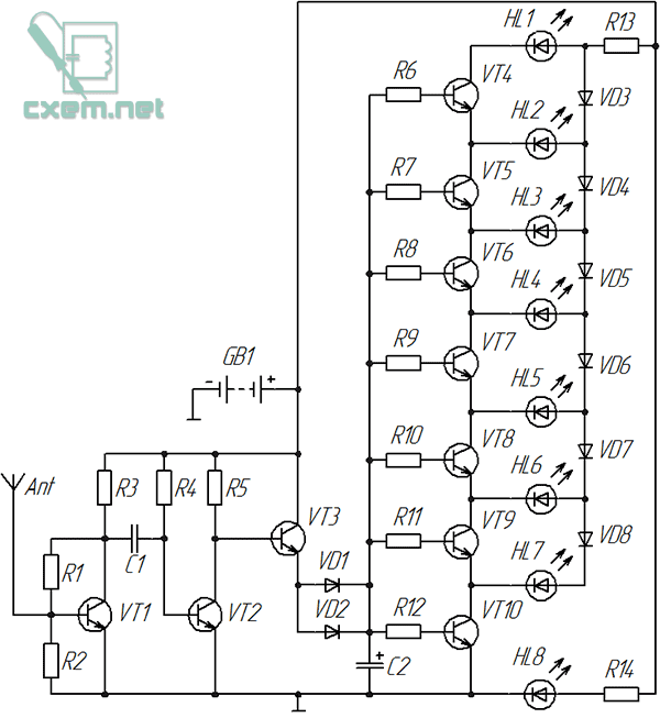
An amplifier based on transistors is assembled here.
KT3102EM was used as transistor VT1. I decided to choose it because it has very good sensitivity.
All other transistors (VT2-VT10) are 2N3904.
Let's consider the indication circuit: transistors VT4-VT10 are the key elements here, each of which turns on the corresponding LED when a signal arrives. Any transistors of this scale can be used, even KT315, but when soldering it is more convenient to use transistors in the TO-92 package due to the convenient location of the terminals.
Threshold diodes (VD3-VD8) are used here, and therefore only one LED lights up at any time, indicating the signal level. True, this does not happen in relation to the radiation of a mobile phone, since the signal constantly pulsates at a high frequency, causing almost all LEDs to glow.

The number of “LED-transistor” cells should not be more than eight. The values of the base resistors are the same here and amount to 1 kOhm. The rating will depend on the gain of the transistors; when using KT315, 1 kOhm resistors should also be used.
It is advisable to use Schottky diodes as diodes VD1, VD2, since they have a lower voltage drop, but everything works even when using the common 1N4001. One of them (VD1 or VD2) can be excluded if the indication is too high.
All other diodes (VD3 - VD8) are the same 1N4001, but you can try using any you have on hand.
Capacitor C2 is electrolytic, its optimal capacity is from 10 to 22 μF, it delays the extinguishing of the LEDs for a fraction of a second.
The value of resistors R13 AND R14 depends on the current consumed by the LEDs, and will range from 300 to 680 Ohms, but the value of resistor R13 can be changed depending on the supply voltage or if the LED scale is insufficiently bright. Instead, you can solder a trimmer resistor and achieve the desired brightness.

There is a switch on the board that turns on a certain “turbo mode” and passes current bypassing resistor R13, as a result of which the brightness of the scale increases. I use it when powered by a Krona battery, when it runs low and the LED scale dims. The switch is not indicated on the diagram, because it is not required.
Once power is applied, the HL8's LED will light up immediately and simply indicate that the device is turned on.
The circuit is powered with voltage from 5 to 9 Volts.
Next, you can make a case for it, for example, from transparent plastic, and foil PCB can be used as a base. By connecting an antenna to the metallization of the board, it may be possible to increase the sensitivity of this indicator of high-frequency radiation.
By the way, it also reacts to microwave radiation.
List of radioelements
| Designation | Type | Denomination | Quantity | Note | Shop | My notepad |
|---|---|---|---|---|---|---|
| VT1 | Bipolar transistor | KT3102EM | 1 | To notepad | ||
| VT2-VT10 | Bipolar transistor | 2N3904 | 9 | To notepad | ||
| VD1 | Schottky diode | 1N5818 | 1 | Any Schottky diode | To notepad | |
| VD2-VD8 | Rectifier diode | 1N4001 | 7 | To notepad | ||
| C1 | Ceramic capacitor | 1 - 10 nF | 1 | To notepad | ||
| C2 | Electrolytic capacitor | 10 - 22 µF | 1 | To notepad | ||
| R1, R4 | Resistor | 1 MOhm | 2 | To notepad | ||
| R2 | Resistor | 470 kOhm | 1 | To notepad | ||
| R3, R5 | Resistor | 10 kOhm | 2 |
I was very surprised when my simple homemade detector-indicator went off scale next to a working microwave oven in our work canteen. It’s all shielded, maybe there’s some kind of malfunction? I decided to check out my new stove; it had hardly been used. The indicator also deviated to the full scale!
 I assemble such a simple indicator in a short time every time I go to field tests of transmitting and receiving equipment. It helps a lot in work, you don’t have to carry a lot of equipment with you, it’s always easy to check the functionality of the transmitter with a simple homemade product (where the antenna connector is not fully screwed in, or you forgot to turn on the power). Customers really like this style of retro indicator and have to leave it as a gift.
The advantage is the simplicity of the design and the lack of power. Eternal device.
It’s easy to do, much simpler than the exact same “Detector from a network extension cord and a bowl of jam” in the mid-wave range. Instead of a network extension cord (inductor) - a piece of copper wire; by analogy, you can have several wires in parallel, it won’t be any worse. The wire itself in the form of a circle 17 cm long, at least 0.5 mm thick (for greater flexibility I use three such wires) is like oscillatory circuit below, and with a loop antenna of the upper part of the range, which ranges from 900 to 2450 MHz (I did not check the performance above). It is possible to use a more complex directional antenna and input matching, but such a deviation would not correspond to the title of the topic. A variable, built-in or just a capacitor (aka a basin) is not needed, for a microwave there are two connections next to each other, already a capacitor.
There is no need to look for a germanium diode; it will be replaced by a PIN diode HSMP: 3880, 3802, 3810, 3812, etc., or HSHS 2812 (I used it). If you want to move above the frequency of the microwave oven (2450 MHz), choose diodes with a lower capacitance (0.2 pF), HSMP -3860 - 3864 diodes may be suitable. When installing, do not overheat. It is necessary to solder spot-quickly, in 1 second.
Instead of high-impedance headphones there is a dial indicator. The magnetoelectric system has the advantage of inertia. The filter capacitor (0.1 µF) helps the needle move smoothly. The higher the indicator resistance, the more sensitive the field meter (the resistance of my indicators ranges from 0.5 to 1.75 kOhm). The information contained in a deviating or twitching arrow has a magical effect on those present.
Such a field indicator, installed next to the head of a person talking on a mobile phone, will first cause amazement on the face, perhaps bring the person back to reality, and save him from possible diseases.
If you still have strength and health, be sure to point your mouse at one of these articles.
Instead of a pointer device, you can use a tester that will measure DC voltage at the most sensitive limit.
 |
| Microwave indicator circuit with LED. |
 |
| Microwave indicator with LED. |
Tried it LED as indicator. This design can be designed in the form of a keychain using a flat 3-volt battery, or inserted into an empty mobile phone case. The standby current of the device is 0.25 mA, the operating current directly depends on the brightness of the LED and will be about 5 mA. The voltage rectified by the diode is amplified by the operational amplifier, accumulated on the capacitor and opens the switching device on the transistor, which turns on the LED.
If the dial indicator without a battery deviated within a radius of 0.5 - 1 meter, then the color music on the diode moved up to 5 meters, both from the cell phone and from the microwave oven. I was not mistaken about color music, see for yourself that the maximum power will only be when talking on a mobile phone and in the presence of extraneous loud noise.
Adjustment.
I collected several such indicators, and they worked immediately. But there are still nuances. When turned on, the voltage on all pins of the microcircuit, except the fifth, should be equal to 0. If this condition is not met, connect the first pin of the microcircuit through a 39 kOhm resistor to minus (ground). It happens that the configuration of microwave diodes in the assembly does not coincide with the drawing, so you must adhere to electrical diagram, and before installation, I would advise you to ring the diodes for their compliance.
For ease of use, you can worsen the sensitivity by reducing the 1 mOhm resistor, or reducing the length of the wire turn. With the given field values, microwave base telephone stations can be sensed within a radius of 50 - 100 m.
With such an indicator, you can draw up an environmental map of your area and highlight places where you can’t hang out with strollers or stay with children for a long time.
 |
Be under base station antennas |
Analog level indicator.

I decided to try to make the microwave indicator a little more complex, for which I added an analog level meter to it. For convenience, I used the same element base. The circuit shows three DC operational amplifiers with different gains. In the layout, I settled on 3 stages, although you can plan a 4th one using the LMV 824 microcircuit (4th op-amp in one package). Having used power from 3, (3.7 telephone battery) and 4.5 volts, I came to the conclusion that it is possible to do without a key stage on a transistor. Thus, we got one microcircuit, a microwave diode and 4 LEDs. Taking into account the conditions of strong electromagnetic fields in which the indicator will operate, I used blocking and filtering capacitors for all inputs, feedback circuits and op-amp power supply.
Adjustment.
When turned on, the voltage on all pins of the microcircuit, except the fifth, should be equal to 0. If this condition is not met, connect the first pin of the microcircuit through a 39 kOhm resistor to minus (ground). It happens that the configuration of microwave diodes in the assembly does not coincide with the drawing, so you need to adhere to the electrical diagram, and before installation I would advise you to ring the diodes to ensure their compliance.
This prototype has already been tested.
The interval from 3 illuminated LEDs to completely extinguished ones is about 20 dB.
Power supply from 3 to 4.5 volts. Standby current from 0.65 to 0.75 mA. The operating current when the 1st LED lights up is from 3 to 5 mA.
This microwave field indicator on a chip with a 4th op amp was assembled by Nikolai.
Here is his diagram.
 |
| Dimensions and pin markings of the LMV824 microcircuit. |
 |
| Installation of microwave indicator on the LMV824 chip. |
The MC 33174D microcircuit, which has similar parameters and includes four operational amplifiers, is housed in a dip package and is larger in size and therefore more convenient for amateur radio installation. The electrical configuration of the pins completely coincides with the L MV 824 microcircuit. Using the MC 33174D microcircuit, I made a layout of a microwave indicator with four LEDs. A 9.1 kOhm resistor and a 0.1 μF capacitor in parallel with it are added between pins 6 and 7 of the microcircuit. The seventh pin of the microcircuit is connected through a 680 Ohm resistor to the 4th LED. The standard size of the parts is 06 03. The breadboard is powered by a lithium cell of 3.3 - 4.2 volts.
 |
| Indicator on the MC33174 chip. |
 |
| Reverse side. |

The original design of the economical field indicator is a souvenir made in China. This inexpensive toy contains: a radio, a clock with a date, a thermometer and, finally, a field indicator. The unframed, flooded microcircuit consumes negligibly little energy, since it operates in a timing mode; it reacts to turning on a mobile phone from a distance of 1 meter, simulating a few seconds of LED indication of an emergency alarm with headlights. Such circuits are implemented on programmable microprocessors with a minimum number of parts.
Addition to comments.
Selective field meters for the amateur band 430 - 440 MHz
and for the PMR band (446 MHz).
Indicators of microwave fields for amateur bands from 430 to 446 MHz can be made selective by adding an additional circuit L to Sk, where Lk is a turn of wire with a diameter of 0.5 mm and a length of 3 cm, and Sk is a trimming capacitor with a nominal value of 2 - 6 pF . The turn of wire itself, as an option, can be made in the form of a 3-turn coil, with a pitch wound on a mandrel with a diameter of 2 mm with the same wire. An antenna in the form of a piece of wire 17 cm long must be connected to the circuit through a 3.3 pF coupling capacitor.
 |
| Range 430 - 446 MHz. Instead of a turn, there is a step-wound coil. |
 |
| Diagram for ranges 430 - 446 MHz. |
 |
| Frequency range mounting 430 - 446 MHz. |
By the way, if you are serious about microwave measurements of individual frequencies, you can use selective SAW filters instead of a circuit. In the capital's radio stores their assortment is currently more than sufficient. You will need to add an RF transformer to the circuit after the filter.
But this is another topic that does not correspond to the title of the post.