What is idle speed when welding? Types and design of welding transformers
1.1. General information.
Depending on the type of current used for welding, there are DC and AC welding machines. Welding machines using low direct currents are used when welding thin sheet metal, in particular roofing and automotive steel. The welding arc in this case is more stable and welding can occur both with direct and reverse polarity of the supplied constant voltage.
You can weld on direct current with electrode wire without coating and with electrodes that are designed for welding metals with direct or alternating current. To make the arc burn at low currents, it is desirable to have an increased open-circuit voltage U xx up to 70...75 V on the welding winding. To rectify alternating current, as a rule, bridge rectifiers with powerful diodes with cooling radiators are used (Fig. 1).
Fig.1 Schematic electrical diagram of a bridge rectifier of a welding machine, indicating polarity when welding thin sheet metal
To smooth out voltage ripples, one of the CA terminals is connected to the electrode holder through a T-shaped filter consisting of an inductor L1 and a capacitor C1. Choke L1 is a coil of 50...70 turns of a copper bus with a tap from the middle with a cross section of S = 50 mm 2 wound on a core, for example, from a step-down transformer OCO-12, or more powerful. The larger the cross-section of the iron of the smoothing choke, the less likely it is that its magnetic system will go into saturation. When the magnetic system enters saturation at high currents (for example, when cutting), the inductance of the inductor decreases abruptly and, accordingly, current smoothing will not occur. The arc will burn unsteadily. Capacitor C1 is a battery of capacitors such as MBM, MBG or similar with a capacity of 350-400 μF for a voltage of at least 200 V
Characteristics of powerful diodes and their imported analogues can be found. Or from the link you can download a guide to diodes from the series “Helping the Radio Amateur No. 110”
To rectify and smoothly regulate the welding current, circuits based on powerful controlled thyristors are used, which allow you to change the voltage from 0.1 xx to 0.9U xx. In addition to welding, these regulators can be used to charge batteries, power electric heating elements and other purposes.
AC welding machines use electrodes with a diameter of more than 2 mm, which makes it possible to weld products with a thickness of more than 1.5 mm. During the welding process, the current reaches tens of amperes and the arc burns quite steadily. Such welding machines use special electrodes that are intended only for welding with alternating current.
For normal operation of the welding machine, a number of conditions must be met. The output voltage must be sufficient to reliably ignite the arc. For an amateur welding machine U xx =60...65V. For work safety, a higher output no-load voltage is not recommended; for industrial welding machines, for comparison, U xx can be 70..75 V..
Welding voltage value I St. should ensure stable arc burning, depending on the diameter of the electrode. The welding voltage Ust can be 18...24 V.
The rated welding current should be:
I St =KK 1 *d e, Where
I St.- welding current value, A;
K 1 =30...40- coefficient depending on the type and size of the electrode d e, mm.
Current short circuit should not exceed the rated welding current by more than 30...35%.
It has been noted that stable arcing is possible if the welding machine has a falling external characteristic, which determines the relationship between the current and voltage in the welding circuit. (Fig.2)

Fig.2 Falling external characteristic of the welding machine:
At home, as practice shows, it is quite difficult to assemble a universal welding machine for currents ranging from 15...20 to 150...180 A. In this regard, when designing a welding machine, one should not strive to completely cover the range of welding currents. It is advisable at the first stage to assemble a welding machine for working with electrodes with a diameter of 2...4 mm, and at the second stage, if it is necessary to work at low welding currents, supplement it with a separate rectifier device with smooth control of the welding current.
Analysis of the designs of amateur welding machines at home allows us to formulate a number of requirements that must be met during their manufacture:
- Small dimensions and weight
- Power supply 220 V
- The duration of operation should be at least 5...7 electrodes d e =3...4 mm
The weight and dimensions of the device directly depend on the power of the device and can be reduced by reducing its power. The operating time of the welding machine depends on the core material and the heat resistance of the insulation of the winding wires. To increase welding time, it is necessary to use steel with high magnetic permeability for the core.
1. 2. Selecting the type of core.
For the manufacture of welding machines, rod-type magnetic cores are mainly used, since their design is more technologically advanced. The core of the welding machine can be assembled from electrical steel plates of any configuration with a thickness of 0.35...0.55 mm and tightened with pins insulated from the core (Fig. 3).

Fig.3 Rod type magnetic core:
When selecting a core, it is necessary to take into account the dimensions of the “window” to fit the windings of the welding machine, and the area of the transverse core (yoke) S=a*b, cm 2.
As practice shows, you should not choose the minimum values S = 25..35 cm 2, since the welding machine will not have the required power reserve and it will be difficult to obtain high-quality welding. And hence, as a consequence, the possibility of overheating of the device after short operation. To prevent this from happening, the cross-section of the welding machine core should be S = 45..55 cm 2. Although the welding machine will be somewhat heavier, it will work reliably!
It should be noted that amateur welding machines using toroidal-type cores have electrical characteristics 4...5 times higher than those of a rod type, and hence small electrical losses. It is more difficult to make a welding machine using a toroidal type core than with a rod type core. This is mainly due to the placement of the windings on the torus and the complexity of the winding itself. However, with the right approach they give good results. The cores are made from transformer strip iron, rolled into a torus-shaped roll.

Rice. 4 Toroidal magnetic core:
To increase the internal diameter of the torus ("window"), a piece of steel tape is unwinded from the inside and wound onto the outer side of the core (Fig. 4). After rewinding the torus, the effective cross-section of the magnetic circuit will decrease, so you will have to partially wind the torus with iron from another autotransformer until the cross-section S is equal to at least 55 cm 2.
The electromagnetic parameters of such iron are most often unknown, so they can be determined experimentally with sufficient accuracy.
1. 3. Selection of winding wires.
For the primary (network) windings of the welding machine, it is better to use a special heat-resistant copper winding wire in cotton or fiberglass insulation. Wires in rubber or rubber-fabric insulation also have satisfactory heat resistance. It is not recommended to use wires in polyvinyl chloride (PVC) insulation for work at elevated temperatures due to its possible melting, leakage from the windings and short circuit of the turns. Therefore, the polyvinyl chloride insulation from the wires must either be removed and the wires wrapped along the entire length with cotton insulating tape, or not removed at all, but wrapped around the wire over the insulation.
When selecting the cross-section of the winding wires, taking into account the periodic operation of the welding machine, a current density of 5 A/mm2 is allowed. The power of the secondary winding can be calculated using the formula P 2 =I St *U St. If welding is carried out with an electrode dе=4 mm, at a current of 130...160 A, then the power of the secondary winding will be: P 2 =160*24=3.5...4 kW, and the power of the primary winding, taking into account losses, will be of the order of 5...5.5 kW. Based on this, the maximum current in the primary winding can reach 25 A. Therefore, the cross-sectional area of the primary winding wire S1 must be at least 5..6 mm2.
In practice, it is advisable to take a slightly larger cross-sectional area of the wire, 6...7 mm 2 . For winding, a rectangular busbar or copper winding wire with a diameter of 2.6...3 mm is used, excluding insulation. The cross-sectional area S of the winding wire in mm2 is calculated by the formula: S=(3.14*D2)/4 or S=3.14*R2; D is the diameter of the bare copper wire, measured in mm. If there is no wire of the required diameter, winding can be carried out in two wires of a suitable cross-section. When using aluminum wire, its cross-section must be increased by 1.6..1.7 times.
The number of turns of the primary winding W1 is determined from the formula:
W 1 =(k 2 *S)/U 1, Where
k 2 - constant coefficient;
S- cross-sectional area of the yoke in cm 2
You can simplify the calculation by using a special program for the calculation: Welding calculator
When W1=240 turns, taps are made from 165, 190 and 215 turns, i.e. every 25 turns. A larger number of network winding taps, as practice shows, is impractical.
This is due to the fact that by reducing the number of turns of the primary winding, both the power of the welding machine and U xx increase, which leads to an increase in the arc voltage and a deterioration in the quality of welding. By changing only the number of turns of the primary winding, it is not possible to cover the range of welding currents without deteriorating the quality of welding. In this case, it is necessary to provide for switching the turns of the secondary (welding) winding W 2.
The secondary winding W 2 must contain 65...70 turns of an insulated copper busbar with a cross-section of at least 25 mm2 (preferably a cross-section of 35 mm2). A flexible stranded wire, such as a welding wire, and a three-phase stranded power cable are also suitable for winding the secondary winding. The main thing is that the cross-section of the power winding is not less than required, and that the wire insulation is heat-resistant and reliable. If the wire cross-section is insufficient, winding in two or even three wires is possible. When using aluminum wire, its cross-section must be increased by 1.6...1.7 times. The leads of the welding winding are usually inserted through copper lugs under terminal bolts with a diameter of 8...10 mm (Fig. 5).
1.4. Features of winding windings.
There are the following rules for winding the windings of a welding machine:
- Winding should be done along an insulated yoke and always in the same direction (for example, clockwise).
- Each winding layer is insulated with a layer of cotton insulation (fiberglass, electrical cardboard, tracing paper), preferably impregnated with bakelite varnish.
- The terminals of the windings are tinned, marked, secured with cotton braid, and a cotton cambric is additionally put on the terminals of the network winding.
- If the wire insulation is of poor quality, winding can be done in two wires, one of which is a cotton cord or cotton thread for fishing. After winding one layer, the winding with cotton thread is fixed with glue (or varnish) and only after it has dried, the next row is wound.
The network winding on a rod-type magnetic core can be positioned in two main ways. The first method allows you to obtain a more “hard” welding mode. The network winding consists of two identical windings W1, W2, located on different sides of the core, connected in series and having the same wire cross-section. To adjust the output current, taps are made on each of the windings, which are closed in pairs ( Rice. 6 a, b)

Rice. 6. Methods for winding CA windings on a rod-type core:
The second method of winding the primary (network) winding involves winding a wire on one side of the core ( rice. 6 c, d). In this case, the welding machine has a steeply falling characteristic, welds “softly”, the length of the arc has less influence on the value of the welding current, and, consequently, on the quality of welding.
After winding the primary winding of the welding machine, it is necessary to check for the presence of short-circuited turns and the correct number of turns. The welding transformer is connected to the network through a fuse (4...6 A) and if there is an AC ammeter. If the fuse burns out or gets very hot, this is a clear sign of a short-circuited turn. In this case, the primary winding must be rewound, paying special attention to the quality of the insulation.
If the welding machine makes a loud noise and the current consumption exceeds 2...3 A, then this means that the number of turns of the primary winding is underestimated and it is necessary to wind up a certain number of turns. A working welding machine should consume no more than 1..1.5 A current at idle, not get hot and not make a strong buzz.
The secondary winding of the welding machine is always wound on both sides of the core. According to the first winding method, the secondary winding consists of two identical halves, connected counter-parallel to increase the stability of the arc (Fig. 6 b). In this case, the wire cross-section can be taken slightly smaller, that is, 15..20 mm 2. When winding the secondary winding using the second method, first 60...65% of the total number of its turns is wound on the side of the core free from windings.
This winding serves mainly to ignite the arc, and during welding, due to a sharp increase in magnetic flux dissipation, the voltage on it drops by 80...90%. The remaining number of turns of the secondary winding in the form of an additional welding winding W 2 is wound on top of the primary. Being a power supply, it maintains the welding voltage and, consequently, the welding current within the required limits. The voltage across it drops in welding mode by 20...25% relative to the no-load voltage.
Winding the windings of a welding machine on a toroidal core can also be done in several ways ( Rice. 7).

Methods for winding the windings of a welding machine on a toroidal core.
Switching windings in welding machines is easier to do with the help of copper tips and terminals. Copper lugs at home can be made from copper tubes of a suitable diameter with a length of 25...30 mm, securing the wires in them by crimping or soldering. When welding under different conditions (high or low current network, long or short supply cable, its cross-section, etc.), by switching the windings, the welding machine is adjusted to the optimal welding mode, and then the switch can be set to the neutral position.
1.5. Setting up the welding machine.
Having manufactured a welding machine, a home electrician must set it up and check the quality of welding with electrodes of various diameters. The setup process is as follows. To measure welding current and voltage you need: an AC voltmeter of 70...80 V and an AC ammeter of 180...200 A. The connection diagram for measuring instruments is shown in ( Rice. 8)

Rice. 8 Schematic diagram connecting measuring instruments when setting up the welding machine
When welding with different electrodes, the values of the welding current - I St and welding voltage U St are taken, which must be within the required limits. If the welding current is small, which happens most often (the electrode sticks, the arc is unstable), then in this case, by switching the primary and secondary windings, the required values are set, or the number of turns of the secondary winding is redistributed (without increasing them) towards increasing the number of turns wound on top of the network windings
After welding, it is necessary to check the quality of welding: the depth of penetration and the thickness of the deposited metal layer. For this purpose, the edges of the welded products are broken or sawed. It is advisable to create a table based on the measurement results. Analyzing the data obtained, the optimal welding modes for electrodes of different diameters are selected, remembering that when welding with electrodes, for example, with a diameter of 3 mm, electrodes with a diameter of 2 mm can be cut, because The cutting current is 30...25% higher than the welding current.
The welding machine must be connected to the network using a wire with a cross-section of 6...7 mm through an automatic machine with a current of 25...50 A, for example AP-50.
The diameter of the electrode, depending on the thickness of the metal being welded, can be selected based on the following ratio: de=(1...1.5)*B, where B is the thickness of the metal being welded, mm. The arc length is selected depending on the diameter of the electrode and is on average equal to (0.5...1.1) de. It is recommended to weld with a short arc of 2...3 mm, the voltage of which is 18...24 V. Increasing the length of the arc leads to a violation of the stability of its combustion, increased losses due to waste and spatter, and a decrease in the depth of penetration of the base metal. The longer the arc, the higher the welding voltage. The welding speed is selected by the welder depending on the grade and thickness of the metal.
When welding with straight polarity, the plus (anode) is connected to the part and the minus (cathode) to the electrode. If it is necessary for less heat to be generated on the parts, for example, when welding thin-sheet structures, then reverse polarity welding is used. In this case, the minus (cathode) is connected to the part being welded, and the plus (anode) is connected to the electrode. This not only ensures less heating of the part being welded, but also accelerates the process of melting the electrode metal due to the higher temperature of the anode zone and greater heat input.
Welding wires are connected to the welding machine through copper lugs under the terminal bolts on the outside of the welding machine body. Poor contact connections reduce the power characteristics of the welding machine, deteriorate the quality of welding and can cause overheating and even fire of the wires.
With a short length of welding wires (4..6 m), their cross-sectional area should be at least 25 mm 2.
During welding work, it is necessary to comply with fire safety rules, and when setting up the device and electrical safety - during measurements with electrical devices. Welding must be carried out in a special mask with protective glass grade C5 (for currents up to 150...160 A) and mittens. All switching in the welding machine must be done only after disconnecting the welding machine from the network.
2. Portable welding machine based on Latra.
2.1. Design feature.

The welding machine operates from an alternating current network with a voltage of 220 V. A design feature of the device is the use of an unusual form of magnetic circuit, due to which the weight of the entire device is only 9 kg, and the dimensions are 125x150 mm ( Rice. 9).
For the magnetic core of the transformer, strip transformer iron is used, rolled into a roll in the shape of a torus. As is known, in traditional transformer designs, the magnetic circuit is assembled from W-shaped plates. The electrical characteristics of the welding machine, thanks to the use of a torus-shaped transformer core, are 5 times higher than those of devices with W-shaped plates, and losses are minimal.
2.2. Latra improvements.
For the transformer core, you can use a ready-made “LATR” type M2.
Note. All latras have a six-pin block and voltage: at the input 0-127-220, and at the output 0-150 - 250. There are two types: large and small, and are called LATR 1M and 2M. I don’t remember which one is which. But, for welding, you need a large LATR with rewound iron, or, if they are in good condition, then they wind the secondary windings with a bus and after that the primary windings are connected in parallel, and the secondary windings in series. In this case, it is necessary to take into account the coincidence of the directions of currents in the secondary winding. Then you get something similar to a welding machine, although it welds, like all toroidal ones, a little harshly.
You can use a magnetic core in the form of a torus from a burnt-out laboratory transformer. In the latter case, first remove the fence and fittings from the Latra and remove the burnt winding. If necessary, the cleaned magnetic circuit is rewound (see above), insulated with electrical cardboard or two layers of varnished cloth, and the transformer windings are wound. The welding transformer has only two windings. To wind the primary winding, a piece of PEV-2 wire with a length of 170 m and a diameter of 1.2 mm is used ( Rice. 10)

Rice. 10 Winding the windings of the welding machine:
| 1 - primary winding; | 3 - wire coil; |
| 2 - secondary winding; | 4 - yoke |
For ease of winding, the wire is pre-wound on a shuttle in the form of a 50x50 mm wooden strip with slots. However, for greater convenience, you can make a simple device for winding toroidal power transformers
Having wound the primary winding, cover it with a layer of insulation, and then wind the secondary winding of the transformer. The secondary winding contains 45 turns and is wound with copper wire in cotton or glass insulation. Inside the core, the wire is located turn to turn, and outside - with a small gap, which is necessary for better cooling. A welding machine manufactured according to the given method is capable of delivering a current of 80...185 A. The electrical circuit diagram of the welding machine is shown in rice. eleven.

Rice. eleven Schematic diagram of the welding machine.
The work will be somewhat simplified if you manage to purchase a working 9 A Latr. Then remove the fence, current collector slider and mounting hardware from it. Next, the terminals of the primary winding at 220 V are determined and marked, and the remaining terminals are reliably insulated and temporarily pressed to the magnetic circuit so that they are not damaged when winding a new (secondary) winding. The new winding contains the same number of turns of the same brand and the same wire diameter as in the version discussed above. The transformer in this case produces a current of 70...150 A.
The manufactured transformer is placed on an insulated platform in the same casing, having previously drilled holes in it for ventilation (Fig. 12))

Rice. 12 Options for welding machine casing based on "LATRA".
The terminals of the primary winding are connected to the 220 V network using a ShRPS or VRP cable, and an AP-25 circuit breaker should be installed in this circuit. Each terminal of the secondary winding is connected to a flexible insulated wire of the PRG. The free end of one of these wires is attached to the electrode holder, and the free end of the other is attached to the part being welded. This same end of the wire must be grounded for the safety of the welder. The welding machine current is adjusted by connecting pieces of nichrome or constantan wire d=3 mm and 5 m long, rolled into a “snake”, in series in the circuit of the electrode holder wire. The “snake” is attached to a sheet of asbestos. All connections of wires and ballast are made with M10 bolts. By moving the wire connection point along the “snake”, the required current is set. The current can be adjusted using electrodes of different diameters. For welding with such a device, electrodes of the type E-5RAUONII-13/55-2.0-UD1 dd=1...3 mm are used.
When carrying out welding work, to prevent burns, it is necessary to use a fiber protective shield equipped with an E-1, E-2 light filter. A hat, overalls and mittens are required. The welding machine should be protected from dampness and not allowed to overheat. Approximate operating modes with an electrode d=3 mm: for transformers with a current of 80...185 A - 10 electrodes, and with a current of 70...150 A - 3 electrodes. after using the specified number of electrodes, the device is disconnected from the network for at least 5 minutes (preferably about 20).
3. Welding machine from a three-phase transformer.
The welding machine, in the absence of "LATRA", can also be made on the basis of a three-phase step-down transformer 380/36 V, with a power of 1..2 kW, which is designed to power low-voltage power tools or lighting (Fig. 13).

Rice. 13 General view of the welding machine and its core.
Even a specimen with one burnt-out winding will do here. Such a welding machine operates from an alternating current network with a voltage of 220 V or 380 V and with electrodes with a diameter of up to 4 mm allows you to weld metal with a thickness of 1...20 mm.
3.1. Details.
The terminals for the secondary winding terminals can be made from a copper tube d 10...12 mm and 30...40 mm long (Fig. 14).

Rice. 14 Design of the secondary winding terminal of the welding machine.
On one side it should be riveted and a hole d 10 mm should be drilled in the resulting plate. Carefully stripped wires are inserted into the terminal tube and crimped with light blows of a hammer. To improve contact, notches can be made on the surface of the terminal tube with a core. On the panel located at the top of the transformer, replace the standard screws with M6 nuts with two screws with M10 nuts. It is advisable to use copper new screws and nuts. The secondary winding terminals are connected to them.
For the terminals of the primary winding, an additional board is made from sheet PCB 3mm thick ( Fig.15).

Rice. 15 General view of the scarf for the terminals of the primary winding of the welding machine.
10...11 holes d=6mm are drilled into the board and M6 screws with two nuts and washers are inserted into them. After this, the board is attached to the top of the transformer.

Rice. 16 Schematic diagram of the connection of the primary windings of the transformer for voltage: a) 220 V; b) 380 V (secondary winding not specified)
When the device is powered from a 220 V network, its two outer primary windings are connected in parallel, and the middle winding is connected to them in series ( Fig.16).
4. Electrode holder.
4.1. Electrode holder made of d¾" pipe.
The simplest design is an electrical holder made from a d¾" pipe with a length of 250 mm ( Fig.17).
On both sides of the pipe at a distance of 40 and 30 mm from its ends, cut out with a hacksaw a recess half the diameter of the pipe ( Fig.18)

Rice. 18 Drawing of the electrode holder housing made of d¾" pipe
A piece of steel wire d=6 mm is welded to the pipe above the large recess. On the opposite side of the holder, a hole d = 8.2 mm is drilled into which an M8 screw is inserted. The screw is connected to a terminal from the cable going to the welding machine, which is clamped with a nut. A piece of rubber or nylon hose with a suitable internal diameter is placed on top of the pipe.
4.2. Electrode holder made of steel angles.
A convenient and simple-to-design electrode holder can be made from two steel corners 25x25x4 mm ( rice. 19)
Take two such angles, about 270 mm long, and connect them with small angles and bolts with M4 nuts. The result is a box with a cross section of 25x29 mm. In the resulting body, a window for the clamp is cut out and a hole is drilled to install the axis of the clamps and electrodes. The latch consists of a lever and a small key made of a sheet of steel 4 mm thick. This part can also be made from a corner 25x25x4 mm. To ensure reliable contact of the clamp with the electrode, a spring is put on the clamp axis, and the lever is connected to the body with a contact wire.
The handle of the resulting holder is covered with insulating material, which is used as a piece of rubber hose. The electrical cable from the welding machine is connected to the housing terminal and secured with a bolt.
5. Electronic current regulator for welding transformer.
An important design feature of any welding machine is the ability to adjust the operating current. The following methods are known for adjusting the current in welding transformers: shunting using chokes of various types, changing the magnetic flux due to the mobility of the windings or magnetic shunting, using stores of active ballast resistances and rheostats. All these methods have both their advantages and disadvantages. For example, the disadvantage of the latter method is the complexity of the design, the bulkiness of the resistances, their strong heating during operation, and inconvenience when switching.
The most optimal method is to adjust the current stepwise by changing the number of turns, for example, by connecting to taps made when winding the secondary winding of the transformer. However, this method does not allow the current to be adjusted over a wide range, so it is usually used to adjust the current. Among other things, adjusting the current in the secondary circuit of a welding transformer is associated with certain problems. In this case, significant currents pass through the control device, which causes an increase in its dimensions. For the secondary circuit, it is practically impossible to select powerful standard switches that could withstand currents of up to 260 A.
If we compare the currents in the primary and secondary windings, it turns out that the current in the primary winding circuit is five times less than in the secondary winding. This suggests the idea of placing a welding current regulator in the primary winding of the transformer, using thyristors for this purpose. In Fig. Figure 20 shows a diagram of the welding current regulator using thyristors. With extreme simplicity and accessibility of the element base, this regulator is easy to operate and does not require configuration.
Power regulation occurs when the primary winding of the welding transformer is periodically turned off for a fixed period of time at each half-cycle of the current. The average current value decreases. The main elements of the regulator (thyristors) are connected counter and parallel to each other. They are alternately opened by current pulses generated by transistors VT1, VT2.
When the regulator is connected to the network, both thyristors are closed, capacitors C1 and C2 begin to charge through the variable resistor R7. As soon as the voltage on one of the capacitors reaches the avalanche breakdown voltage of the transistor, the latter opens and the discharge current of the capacitor connected to it flows through it. Following the transistor, the corresponding thyristor opens, which connects the load to the network.
By changing the resistance of resistor R7, you can regulate the moment the thyristors are turned on from the beginning to the end of the half-cycle, which in turn leads to a change in the total current in the primary winding of the welding transformer T1. To increase or decrease the adjustment range, you can change the resistance of the variable resistor R7 up or down, respectively.
Transistors VT1, VT2 operating in avalanche mode, and resistors R5, R6 included in their base circuits can be replaced with dinistors (Fig. 21)

Rice. 21 Schematic diagram of replacing a transistor with a resistor with a dinistor, in the current regulator circuit of a welding transformer.
The anodes of the dinistors should be connected to the extreme terminals of resistor R7, and the cathodes should be connected to resistors R3 and R4. If the regulator is assembled using dinistors, then it is better to use devices of the KN102A type.
Old-style transistors such as P416, GT308 have proven themselves well as VT1, VT2, but these transistors, if desired, can be replaced with modern low-power high-frequency transistors that have similar parameters. The variable resistor is SP-2 type, and the fixed resistors are MLT type. Capacitors type MBM or K73-17 for an operating voltage of at least 400 V.
All parts of the device are assembled using hinged mounting on a textolite plate 1...1.5 mm thick. The device has a galvanic connection to the network, so all elements, including thyristor heat sinks, must be isolated from the housing.
A correctly assembled welding current regulator does not require special adjustment, you just need to make sure stable work transistors in avalanche mode or, when using dinistors, in their stable activation.
Descriptions of other designs can be found on the website http://irls.narod.ru/sv.htm, but I would like to warn you right away that many of them have at least controversial issues.
Also on this topic you can see:
http://valvolodin.narod.ru/index.html - many GOST standards, diagrams of both home-made devices and factory ones
http://www.y-u-r.narod.ru/Svark/svark.htm the same site for a welding enthusiast
When writing the article, some of the materials from the book by Pestrikov V.M. “Home electrician and not only...” were used.All the best, write to © 2005
The open circuit voltage of a welding inverter is the voltage between the positive and negative output contacts of the device when there is no arc. For a welding inverter in good condition, it should be within the limits specified in the manufacturer’s instructions. Typically this voltage is from 40 V to 90 V. This rating ensures easy ignition of the arc when welding metal. This also creates safety for the welder.
Open circuit voltage: how it occurs and what it affects
The open circuit voltage is obtained by converting the mains voltage (220 V or 380 V, 50 Hz) in two series converters, first into direct current voltage and then into alternating current with a frequency of 20-50 kHz. Then the high-frequency voltage is supplied to the regulator, which maintains the required voltage at the output terminals and the specified current when the arc is ignited.

Many people believe that this parameter only affects the ease of igniting the arc; the higher the voltage, the easier it is to ignite the arc. Working conditions for welders when installing structures are far from ideal. Accidentally touching live parts with excessive voltage may lead to an accident.
For many inverter models, the no-load voltage and operating current are directly related. When welding metal covered with a thick layer of rust or paint, the arc is difficult to ignite.
If in this situation the open-circuit voltage is increased, the operating current will be excessive, and instead of a high-quality metal connection, slag and pores may form.
Return to contents
What determines the correct selection of the mode?
A correctly set idle mode ensures high-quality combustion of the electrode and a clearly defined droplet transfer of metal into the weld pool, forming a reliable connection with weld root penetration. The formation of spatter when igniting and breaking the arc is minimal; the surface of the parts being welded in the weld area requires almost no additional cleaning. One of the main signs of a correctly selected mode is the characteristic hissing sound when the arc burns.

Three-phase welding rectifier with no-load voltage regulation by sectioning the turns of the transformer windings.
Some models of welding inverter have an additional protective function against electric shock to the welder at increased open circuit voltage. The device automatically reduces the voltage to a safe value when an emergency occurs and restores it when it disappears. Devices with increased open circuit voltage are used when welding with electrodes with refractory coating used to work with specific alloys.
Certain inverter models are equipped with a circuit for better arc ignition. Such devices were used on transformer welding machines with alternating and direct current. The oscillator converts the mains supply voltage into a voltage of 2.5-3 kV with a frequency of 150-300 kHz and outputs it to the output terminals in pulses lasting several tens of milliseconds. The oscillator consists of a low-frequency step-up transformer connected to oscillatory circuit, and a spark gap with tungsten contacts. At the output there are capacitors that pass high-frequency currents and limit the low-frequency current from the welding machine.
Such devices also provide protection against electric shock. The power consumption of the oscillators is 250-300 W, which slightly increases the total power consumption of the welding inverter. Oscillators can be purchased as a separate unit or made independently.
Return to contents
Possible malfunctions and their causes
The causes of problems with the inverter may arise due to:
- malfunction of the inverter itself;
- unsatisfactory condition of welding cables and device power circuit.

Thermal deformation and voltage at the output of the device are inextricably linked. Due to voltage surges, the temperature of the arc changes, the metal either does not warm up to the required temperature, or burns out, forming slag and pores. Troubleshooting methods depend on the problem found. The simplest reason may be poor contact in the connections of the welding cables with alligator clips and plugs for connecting to the inverter. It leads to the appearance of deformations during welding. Typically, such a defect manifests itself in sharp non-periodic jumps in the welding current, spontaneous attenuation of the arc, which can lead to poor-quality connections, deformation and stress when welding parts from uneven heating.
The solution is simple and can be done independently. To eliminate it, you need to remove the protective insulating handles, disconnect the cable and inspect the connection points. If there are oxides and traces of heating, the surfaces must be cleaned with emery cloth and assembled, carefully tightening the connecting bolts. Cables with broken or broken wires and damaged insulation must be replaced with similar ones. It is better to keep the cable length the same. Many inverter models are designed for a strictly defined inductive reactance load and can change the operating parameters when the cable length changes.
The next reason may be a malfunction of the device itself. To determine the operability of the device, it is necessary to measure the voltage at the output terminals of the inverter and the voltage in the supply network with the device. At normal mains voltage, a low voltage at the inverter output will indicate a malfunction of the device. It is better to entrust inverter repair to specialists from the service center.
If the voltage at the inverter output is within acceptable limits at normal supply voltage, you should carefully check the supply voltage supply circuit to the device from the power supply input point or meter. The minimum power consumption of devices in welding mode is within 4-5 kW. The required cross-section of copper supply wires for such power must be at least 2.5 mm 2 with a long-term permissible operating current of 25 A throughout the entire power circuit. A cable with a smaller cross-section will heat up quickly and the voltage loss on it will increase.
It is imperative to check the quality of all connections along the power supply circuit. Weak twisting or other types of poor-quality connections can also create problems during welding work and lead to fire. Detachable connections from a plug-socket pair must be of a new type with an increased diameter of electrically conductive pins on the plugs. Old type forks cannot withstand the load under long-term operating conditions. Sockets must also be of the appropriate type. The length of the power supply lines cannot be more than 50 m, unless otherwise specified in the technical documentation for the device.
In rural areas, abnormal operation of inverters is often observed due to overloaded common power lines and low network voltage.
If, when trying to ignite an arc, the supply voltage drops to an unacceptably low value at the input point, this indicates insufficient capacity of the common line and its overload.
Sometimes voltage stabilizers can help in such a situation. The effectiveness of stabilizers also depends on several reasons and is not always justified. The total power consumption of the kit from the power supply network will be the power of the welding device plus losses in the stabilization device. Electricity costs will increase, overload of common lines will increase, which will further reduce the input voltage.
Before deciding to use such a device in conjunction with welding equipment, it is advisable to contact the electrical network with a written statement about poor-quality power supply.
In modern literature you can find a lot of material on welding. IN last years a number of articles devoted to the improvement and calculation of elements of welding transformers. I offer the most important thing: how and from what at home make welding transformers. All welding transformer circuits described below have been practically tested and are actually suitable for manual electric welding. Some of the schemes have been developed “among the people” for decades and have become a kind of “classic” of independent “transformer construction”.
Like any transformer, a welding transformer consists of primary and secondary (possibly with taps) windings wound on a large magnetic core made of transformer iron. From ordinary transformer welding is distinguished by its operating mode: it works in arc mode, i.e. at almost maximum possible power. And hence strong vibrations, intense heating, and the need to use large-section wire. Such a transformer is powered from single-phase network 220-240 V. The output voltage of the secondary winding in idle mode (idle) (when no load is connected to the output) for homemade welders is, as a rule, in the range of 45-50 V, less often up to 70 V. In general, the output voltages for industrial welding units are limited (80 V for alternating voltage, 90 V for direct voltage). Therefore, large stationary units have an output of 60-80 V.
The main power characteristic of the welding transformer It is customary to consider the output current of the secondary winding in arc mode (welding mode). In this case, an electric arc burns in the gap between the end of the electrode and the metal being welded. The gap size is 0.5...1.1 d (d is the diameter of the electrode), it is maintained manually. For portable structures, operating currents are 40-200 A. The welding current is determined by the power of the transformer. The choice of the diameter of the electrodes used and the optimal thickness of the metal being welded depend on the output current of the welding transformer.
The most common are electrodes with 3 mm steel rods (“troika”), which require currents of 90-150 A (usually 100-130 A). In skillful hands, the “troika” will burn at 75 A. At currents greater than 150 A, such electrodes can be used for cutting metal (thin sheets of iron 1-2 mm can be cut at lower currents). When working with a 3 mm electrode, a current of 20-30 A (usually about 25 A) flows through the primary winding of the transformer.
If the output current is lower than required, then the electrodes begin to “stick” or “glue”, welding their tips to the metal being welded: thus, the welding transformer begins to operate with dangerous overload in short circuit mode. At currents higher than permissible, the electrodes begin to cut the material: this can ruin the entire product.
For electrodes with a 2 mm iron rod, a current of 40-80 A (usually 50-70 A) is required. They can accurately weld thin steel 1-2 mm thick. 4 mm electrodes work well at a current of 150-200 A. Higher currents are used for less common (05-6 mm) electrodes and metal cutting.
In addition to power, an important property of a welding transformer is its dynamic characteristics. The dynamic characteristics of the transformer largely determine the stability of the arc, and therefore the quality of the welded joints. Among the dynamic characteristics, we can distinguish steeply dipping and gently dipping. When manual welding, inevitable vibrations of the end of the electrode occur and, accordingly, a change in the arc burning length (at the moment of ignition of the arc, when adjusting the arc length, on uneven surfaces, from hand trembling). If the dynamic characteristic of the transformer is steep, then when the arc length fluctuates, minor changes in the operating current occur in the secondary winding of the transformer: the arc burns stably, the weld lies flat. With a flat-sloping or rigid characteristic of the transformer: when the length of the arc changes, the operating current also changes sharply, which changes the welding mode - as a result, the arc burns unstably, the seam is of poor quality, and it is difficult or even impossible to work with such a welding machine manually. For manual arc welding, a steeply falling dynamic characteristic of the transformer is required. Flat-fall type is used for automatic welding.
In general, in real conditions, it is hardly possible to somehow measure or quantify the parameters of the current-voltage characteristics, however, like many other parameters of welding transformers. Therefore, in practice, they are divided into those that weld better and those that work worse. When the transformer works well, welders say: “It welds softly.” This should be understood high quality weld, no metal spattering, the arc burns stably all the time, the metal is deposited evenly. All transformer designs described below are actually suitable for manual arc welding.
Welding transformer operating mode
The operating mode of the welding transformer can be characterized as short-term repetitive. In real conditions, after welding, as a rule, installation, assembly and other work follows. Therefore, after operating in arc mode, the transformer has some time to cool in idle mode. In arc mode, the welding transformer heats up intensely, and in idle mode it cools down, but much more slowly. The situation is worse when the transformer is used for cutting metal, which is very common. In order to cut thick rods, sheets, pipes, etc. with an arc, when the current of a homemade transformer is not too high, you have to overheat the device too much. Any industrial device is characterized by such an important parameter as the operating duration coefficient (OL), measured in %. For domestic factory portable devices weighing 40-50 kg, PR usually does not exceed 20%. This means that the welding transformer can operate in arc mode no more than 20% of the total time, the remaining 80% it must be in idle mode. For most homemade designs, PR should be taken even less. We will consider the intensive operating mode of the transformer to be one when the arc burning time is of the same order as the interruption time.
Homemade welding transformers are made according to different schemes: on U- and W-shaped magnetic wires or toroidal, with different combinations of winding arrangements. The transformer manufacturing scheme and the number of turns of future windings are mainly determined by the available magnetic core. In the future, the article will consider real circuits of homemade transformers and materials for them. Now let’s determine what winding and insulating materials we will need.
Given the high powers, relatively thick wire is used for winding transformers. Developing significant currents during operation, any welder gradually heats up. The heating rate depends on a number of factors, the most important of which is the diameter or cross-sectional area of the winding wires. The thicker the wire, the better it passes current, the less it heats up and, finally, the better it dissipates heat. The main characteristic is the current density (A/mm2): the higher the current density in the wires, the more intense the heating of the transformer occurs. Winding wires can be copper or aluminum. Copper allows you to use 1.5 times higher current density and heats up less: it is better to wind the primary winding with copper wire. In industrial devices, the current density does not exceed 5 A/mm2 for copper wire. For homemade options, 10 A/mm2 for copper can be considered a satisfactory result. As the current density increases, the heating of the transformer sharply accelerates. In principle, for the primary winding you can use a wire through which a current with a density of up to 20 A/mm2 will flow, but then the transformer will heat up to a temperature of 60 ° C after using 2-3 electrodes. If you think that you will have to weld a little, slowly, and you still don’t have better materials, then you can wind the primary winding with wire and with a strong overload. Although this, of course, will inevitably reduce the reliability of the device.
In addition to the section, another important characteristic wire is a method of insulation. The wire can be varnished, wound in one or two layers of thread or fabric, which, in turn, are impregnated with varnish. The reliability of the winding, its maximum overheating temperature, moisture resistance, and insulating qualities greatly depend on the type of insulation (see table). The best insulation is made of fiberglass impregnated with heat-resistant varnish, but such wire is difficult to obtain, and if you buy it, it will not be cheap. The least desirable, but most affordable material for homemade products is ordinary PEL, PEV wires 1.6-2.4 mm in simple varnish insulation. Such wires are the most common; they can be removed from the coils of chokes and transformers of used equipment. When carefully removing old wires from the coil frames, it is necessary to monitor the condition of their coating and additionally insulate slightly damaged areas. If the coils of wire were additionally impregnated with varnish, their turns are stuck together, and when you try to separate them, the hardened impregnation often tears off the wire’s own varnish coating, exposing the metal. In rare cases, in the absence of other options, “homemade workers” wind the primary windings even with a mounting wire in vinyl chloride insulation. Its disadvantages: excess insulation and poor heat dissipation.
The quality of laying the primary winding of a transformer should always be given the greatest attention. The primary winding contains a larger number of turns than the secondary, its winding density is higher, and it heats up more. The primary winding is under high voltage; if it is shorted between turns or the insulation breaks down, for example, through moisture, the entire coil quickly “burns out”. As a rule, it is impossible to restore it without disassembling the entire structure.
The secondary winding is wound with a single or multi-core wire, the cross-section of which provides the required current density. There are several ways to solve this problem. First, you can use a monolithic wire with a cross section of 10-24 mm2 made of copper or aluminum. These rectangular wires (commonly called busbar) are used for industrial welding transformers. However, in most home-made designs, the winding wire has to be pulled many times through the narrow windows of the magnetic circuit. Try to imagine doing this about 60 times with 16mm2 solid copper wire. In this case, it is better to give preference to aluminum wires: they are much softer and cheaper. The second method is to wind the secondary winding with a stranded wire of a suitable cross-section in ordinary vinyl chloride insulation. It is soft, easy to fit, and reliably insulated. True, the synthetic layer takes up excess space in the windows and interferes with cooling. Sometimes for these purposes they use old stranded wires in thick rubber insulation, which are used in powerful three-phase cables. The rubber is easy to remove, and instead of it, wrap the wire with a layer of some thin insulating material. The third way is to make a secondary winding from several single-core wires, approximately the same as those with which the primary winding is wound. To do this, 2-5 wires of 1.6-2.5 mm are carefully tied together with tape and used as one stranded one. This bus of several wires takes up a small volume and is sufficiently flexible, which makes it easy to install. If the required wire is difficult to obtain, then the secondary winding can be made from thin, most common PEV, PEL wires 0.5-0.8 mm, although this will take an hour or two. First, you need to choose a flat surface where you rigidly install two pegs or hooks with a distance between them equal to the length of the secondary winding wire of 20-30 m. Then stretch several dozen strands of thin wire between them without bending, you will get one elongated bundle. Next, disconnect one of the ends of the beam from the support and clamp it into the chuck of an electric or hand drill. At low speeds, the entire bundle is slightly taut and twists into a single wire. After twisting, the length of the wire will decrease slightly. At the ends of the resulting stranded wire, you need to carefully burn the varnish and clean the ends of each wire separately, and then solder everything securely together. After all, it is advisable to insulate the wire by wrapping it along its entire length with a layer of, for example, adhesive tape.
To lay the windings, fasten the wire, inter-row insulation, insulate and fasten the magnetic circuit, you will need a thin, strong and heat-resistant insulating material. In the future, it will be seen that in many designs of welding transformers, the volume of the magnetic circuit windows, into which it is necessary to lay several windings with thick wires, is greatly limited. Therefore, in this “vital” space of the magnetic circuit, every millimeter is valuable. With small core sizes, insulating materials should occupy as little volume as possible, i.e. be as thin and elastic as possible. The common PVC insulating tape can be immediately excluded from use on the heating areas of the transformer. Even with slight overheating, it becomes soft and gradually spreads or is pressed through by wires, and with significant overheating it melts and foams. For insulation and bandage, you can use fluoroplastic, glass and varnished fabric keeper tapes, and regular tape between the rows. Scotch tape can be considered one of the most convenient insulating materials. After all, having an adhesive surface, small thickness, elasticity, it is quite heat-resistant and strong. Moreover, now adhesive tape is sold almost everywhere on reels of various widths and diameters. Small-diameter coils are ideally suited for pulling compact magnetic cores through narrow windows. Two or three layers of tape between the rows of wire practically do not increase the volume of the coils.
And finally, the most important element of any transformer is the magnetic circuit.
As a rule, for homemade products, magnetic cores of old electrical appliances are used, which previously had nothing in common with a welding transformer, for example, large transformers, autotransformers (LATRs), electric motors. The most important parameter of the magnetic circuit is its cross-sectional area (S), through which the magnetic field flow circulates. Magnetic cores with a cross-sectional area of 25-60 cm2 (usually 30-50 cm2) are suitable for the manufacture of a transformer. The larger the cross-section, the greater the flux the magnetic circuit can transmit, the greater the power reserve the transformer has, and the fewer turns its windings contain. Although the optimal cross-sectional area of the magnetic core, the best characteristics when medium power, 30 cm2.
There are standard methods for calculating the parameters of the magnetic circuit and windings for industrial welding circuits. However, these methods are practically not suitable for homemade products. The fact is that the calculation according to the standard methodology is carried out for a given transformer power, and only in a single option. For it, the optimal value of the cross-section of the magnetic circuit and the number of turns are separately calculated. In fact, the cross-sectional area of the magnetic circuit for the same power can be within very wide limits. There is no connection between an arbitrary section and turns in the standard formulas. For homemade welding transformers, any magnetic cores are usually used, and it is clear that it is almost impossible to find a core with “ideal” parameters of standard methods. In practice, it is necessary to select the turns of the windings to match the existing magnetic circuit, thereby setting the required power.
The power of a welding transformer depends on a number of parameters, which cannot be fully taken into account under normal conditions. However, the most important among them are the number of turns of the primary winding and the cross-sectional area of the magnetic circuit. The relationship between the area and the number of turns will determine the operating power. To calculate transformers intended for welding with 3-4 mm electrodes and operating from a single-phase network with a voltage of 220-230 V, I propose to use the following approximate formula, which I obtained based on practical data. Number of turns N=9500/S (cm2). At the same time, for transformers with a large magnetic core area (more than 50 cm2) and relatively high efficiency, it can be recommended to increase the number of turns calculated by the formula by 10-20%. For transformers manufactured on cores with a small area (less than 30 cm), on the contrary, it may be necessary to reduce the number of design turns by 10-20%. In addition, the useful power will be determined by a number of factors: efficiency, voltage of the secondary winding, supply voltage in the network. (Practice shows that the mains voltage, depending on the area and time, can fluctuate between 190-250 V). The resistance of the power line is also important. Comprising only a few Ohms, it has virtually no effect on the readings of the voltmeter, which has a high resistance, but can greatly dampen the power of the transformer. The influence of line resistance can be especially noticeable in places remote from transformer substations (for example, dachas, garage cooperatives, in rural areas where lines are laid with thin wires with a large number of connections). Therefore, initially it is hardly possible to accurately calculate the output current for different conditions - this can only be done approximately. When winding the primary winding, it is better to make its last part with 2-3 taps every 20-40 turns. Thus, you can adjust the power by choosing the best option for yourself, or adapt to the mains voltage. To obtain higher powers from a welding transformer, for example, to operate a 4 mm electrode at currents greater than 150 A, it is necessary to further reduce the number of turns of the primary winding by 20-30%. But it should be remembered that with increasing power, the current density in the wire also increases, and therefore the intensity of heating of the windings. The output current can also be increased slightly by increasing the number of turns of the secondary winding so that the open circuit output voltage increases from the expected 50 V to higher values (70-80 V). 
Having connected the primary winding to the network, it is necessary to measure the no-load current, it should not have a large knowledge (0.1-2 A). (When the welding transformer is connected to the network, a short-term but powerful current surge occurs). In general, in terms of no-load current. it is impossible to judge the output power of a transformer: it can be different even for the same types of transformers. However, by examining the curve of the dependence of the no-load current on the voltage supplying the welder, one can more confidently judge the properties of the transformer. To do this, the primary winding must be connected through the LATR, which will allow the voltage on it to be smoothly changed from 0 to 250 V. The voltage-ampere characteristics of the transformer in no-load mode with different numbers of turns of the primary winding are shown in the figure, where 1 - the winding contains few turns; 2 - the transformer operates at its maximum power; 3, 4 - moderate power. At first, the current curve is hollow, increases almost linearly to a small value, then the rate of increase increases - the curve smoothly bends upward, followed by a rapid increase in current. When the current tends to infinity up to the point of operating voltage 240 V (curve 1), this means that the primary winding contains few turns, and it must be wound up (it must be taken into account that a welding transformer, switched on at the same voltage without LATR, will consume a current of approximately 30% more). If the operating voltage point lies at the bend of the curve, then the transformer will produce its maximum power (curve 2, welding current of the order of 200 A). Curves 3 and 4 correspond to the case when the transformer has a power resource and an insignificant no-load current: most homemade products are focused on this case. In reality, no-load currents are different for different types of welding transformers: most lie in the range of 100-500 mA. I do not recommend setting the no-load current to more than 2 A.
Welding transformers according to the phase of the electric current are divided into single-phase and three-phase, and according to the number of posts - into single-station and multi-station. Single station transformer serves to supply welding current to one workplace and has a corresponding external characteristic.
Multi-station transformer serves for simultaneous power supply of several welding arcs (welding stations) and has a rigid characteristic. To create a stable combustion of the welding arc and ensure a falling external characteristic, a choke is included in the arc welding circuit. For arc welding, welding transformers are divided according to design features into two main groups:
transformers with normal magnetic dispersion, structurally made in the form of two separate devices (transformer and inductor) or in a single common housing;
transformers with developed magnetic dispersion, structurally differing in the method of regulation (with moving coils, with magnetic shunts, with step regulation).
In the USSR, transformers of both groups have found use, and in recent years, mainly transformers in a single-case design with developed magnetic dispersion and with magnetic shunts.
Transformers with normal magnetic leakage.
Transformers with a separate choke. The rigid external characteristic of such a transformer is obtained due to insignificant magnetic scattering and low inductive reactance of the transformer windings. The falling external characteristics are created by a choke having a large inductive reactance.
Technical data of transformers STE-24U and STE-34U with chokes are given in table. 23.
Table 23
Technical characteristics of welding transformers

Continuation of the table. 23

Transformers type STN with built-in choke. Transformers STN-500 and STN-500-1 for manual arc welding and transformers with remote control TSD-500, TSD-2000-2, TSD-1000-3 and TSD-1000-4 for automatic and semi-automatic submerged arc welding. Technical data of these transformers are given in table. 23.
The design diagram of a transformer type STN of the system of Academician V.P. Nikitin and its external static characteristics are shown in Fig. 58. Magnetic scattering and inductive reactance of windings ( 1
And 2
) transformers are small, the external characteristic is rigid. The falling characteristic is created due to the reactivity of the winding 3
, creating inductive reactance. The upper part of the magnetic circuit is also part of the inductor core.

The amount of welding current is regulated by moving the movable package 4
(screw mechanism using a handle 5
). The open circuit voltage of these transformers is 60 - 70 V, and the rated operating voltage U nom = 30 V. Despite the combined magnetic circuit, the transformer and inductor operate independently of each other. In electrical terms, transformers of the STN type do not differ from transformers with separate chokes of the STE type.
For automatic and semi-automatic welding, TSD type transformers are used. A general view of the design of the TSD-1000-3 transformer and its electrical circuit are shown in Fig. 59 and 60.


Transformers of the TSD type have an increased no-load voltage (78 - 85 V), necessary for stable excitation and combustion of the welding arc during automatic submerged arc welding.
The falling external characteristic of the transformer is created by the reactive winding 4
. The TSD type transformer has a special electric drive for remote control of the welding current. To turn on the drive synchronous three-phase electric motor DP with a reduction worm gear, two magnetic starters PMB and PMM, controlled by buttons, are used. The movement of the moving part of the magnetic core package is limited by the limit switches VKB and VKM.
Transformers are equipped with filters to suppress radio interference. In addition to being used for automatic and semi-automatic submerged arc welding, transformers TSD-1000-3 and TSD-2000-2 are used as a power source for heat treatment of welded joints made of alloy and low-alloy steels.
Transformers with developed magnetic dissipation. Transformers type TS and TSK They are mobile rod-type step-down transformers with increased leakage inductance. They are designed for manual arc welding and surfacing, and can be used for submerged arc welding with thin wires. In transformers of the TSK type, a capacitor is connected in parallel to the primary winding to increase the power factor.
Transformers such as TS, TSK do not have moving cores prone to vibration, so they operate almost silently. The welding current is regulated by changing the distance between the moving I and motionless II coils (Fig. 61, c). As the moving coil moves away from the stationary coil, the magnetic leakage fluxes and the inductive reactance of the windings increase. Each position of the moving coil has its own external characteristic. The farther the coils are from each other, the greater the number of magnetic lines of force will be closed through the air spaces without capturing the second winding, and the steeper the external characteristic will be. Open circuit voltage in transformers of this type with coils shifted by 1.5 - 2 V more than the nominal value (60 - 65 V).

The design of the TS-500 transformer and external current-voltage characteristics are shown in Fig. 61,a,b. Technical data of transformers TS and TSK are given in table. 23.
Transformers with magnetic shunts such as STAN, OSTA and STS.
Welding transformers of type STSh-500 (A-760) developed by the Institute of Electric Welding named after E. O. Paton have high performance indicators and a long service life compared to transformers of the TS, TSK, TD types.
The STS rod-type transformer, single-phase, is made in a single-case design and is designed to supply an electric welding arc with alternating current with a frequency of 50 Hz for manual arc welding, cutting and surfacing of metals. In Fig. Figure 62 shows a diagram of the STS-500 transformer.

The magnetic core (transformer core) is made of electrical steel E42 with a thickness of 0.5 mm. Steel sheets are connected with insulated studs.
The coils of the primary winding of the transformer are made of insulated aluminum wire of rectangular cross-section, and the secondary winding is made of bare aluminum busbar, between the turns of which asbestos gaskets are laid, designed to insulate the turns from a short circuit.
The current regulator consists of two movable magnetic shunts located in the window of the magnetic circuit. By rotating the screw clockwise, the shunts move apart, and counterclockwise, they move, and the welding current is gradually regulated. The smaller the distance between the shunts, the lower the welding current, and vice versa. Shunts are made from the same electrical steel as the main line.
To reduce interference to radio receivers that occurs during welding, a capacitive filter of two KBG-I type capacitors is used. The capacitors are mounted on the high voltage side.
Currently, a number of new portable AC welding arc power sources have been created - small-sized transformers. Examples of such transformers are, for example, installation transformers TM-300-P, TSP 1 and TSP-2.
The TM-300-P installation transformer is designed to power the welding arc during single-station arc welding during installation, construction and repair work. The transformer provides a steeply falling external characteristic (with a ratio of short circuit current to the current of the rated operating mode of 1.2 - 1.3) and stepwise regulation of the welding current, which allows welding with electrodes with a diameter of 3, 4 and 5 mm. It is single-hull, lightweight and easy to transport. The TM-300-P transformer has separated windings, which makes it possible to obtain significant inductive reactance to create falling external characteristics. The rod-type magnetic core is assembled from cold-rolled textured steel E310, E320, E330 with a thickness of 0.35 - 0.5 mm. Electrical diagram transformer is shown in Fig. 63.

The primary winding consists of two coils of the same size, completely placed on one magnetic core. The secondary winding also consists of two coils, one of which - the main one - is placed on the magnetic core along with the primary winding, and the second - the reactive one - has three taps and is placed on the other magnetic core.
The reactive secondary winding is significantly removed from the primary winding and has large leakage fluxes, which determine its increased inductive reactance. The amount of welding current is regulated by switching the number of turns of the reactive winding. This current regulation makes it possible to increase the no-load voltage at low currents, providing conditions for stable burning of the welding arc.
The primary winding is made of copper wire with insulation, and the secondary winding is wound with a bus bar. The windings are impregnated with organosilicon varnish FG-9, which makes it possible to increase their heating temperature to 200° C. The magnetic core with the windings is placed on a cart with two wheels. For welding in installation conditions with electrodes with a diameter of 3 and 4 mm A lightweight transformer TSP-1 is used. The transformer is designed for short-term operation with a post load factor of less than 0.5 and electrodes with a diameter of up to 4 mm. The electrical circuit and external characteristics of such a transformer are shown in Fig. 64. Due to the large distance between the primary winding A and secondary winding B Significant magnetic scattering fluxes are formed. The voltage drop due to the inductive resistance of the windings provides steeply falling external characteristics.

The welding current is controlled in steps, just like the welding transformer TM-300-P.
To reduce weight, the transformer design is made of high-quality materials - the magnetic core is made of cold-rolled steel, and the windings are made of aluminum wires with heat-resistant glass insulation.
Technical data of the TSP-1 transformer are given in table. 23.
For welding in installation conditions, small-sized lightweight welding transformers STSh-250 with smooth regulation of welding current, developed by the E. O. Paton Institute of Electric Welding, and TSP-2, developed by the All-Union Scientific Research Institute of Electric Welding Equipment are also produced. The main technical data of these transformers are given in table. 24.
Table 24
Technical characteristics of transformers STS-250 and TSP-2
To perform welding work at various heights in installation conditions, a special welding transformer TD-304 on a skid was created, equipped with remote control of the welding current directly from the electric welder’s workplace. The main technical data of such a transformer in comparison with the TS-300 transformer are given in table. 25.
Table 25
Technical characteristics of transformers TD-304 and TS-300
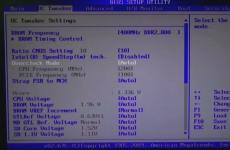
You can test the welding inverter to see what it is capable of. We take the most affordable TIG welding inverter. I will give an example of a device in the photo there IN 256T/ IN 316T.
If you look at the table, it shows where the idle speed is located in the form of an indication. On such devices, the idle speed is programmed by a computer. When you select the desired mode, the idle current is automatically set. It can be checked with a regular voltmeter at the ends of the power wires in the on state. That is, on the holder and the crocodile. The voltage drop should not deviate by more than five volts when igniting the arc and welding.
For example, if you ate a Chinese state employee, you will not find information about idle speed at all. Plus the Amperes are too high. In fact, some won’t even handle Uoni 13/55 electrodes. And why all? This electrode requires an idle current of 70 volts at 80 amps. And such welding machines are designed in such a way that as the current increases, the voltage also increases. In other words, at the highest current they will give you 90 volts. The voltage even before the secondary winding is controlled by a unit that converts the high voltage into the primary winding. Then, under the influence of electromagnetic force, it is transmitted to the secondary winding. The tension removed from her passes on. If the voltage at the input of the primary winding is low, then the output will be low.
Let's consider the primitive VD-306M U3. At low currents of 70-190 A, the voltage is 95 volts plus or minus 3 volts. At high currents of 135-325 A, the idle current is 65 volts plus or minus 3 volts. Moreover, it is stable in all current ranges. No matter how you twist the crank and change the amps to your heart's content, the idle speed will not decrease.

What am I getting at if the welding inverter does not weld well at low currents, the reason is in the control unit described above. As some say, install an additional choke or a ballast at the output. We turn the current up to full and adjust it at the ballast. The extra amperes will be taken over and the idle speed will remain unchanged.
Just for fun, check your welding machine. Throw the probes from the voltmeter onto the power cables and try to cook. See how the voltage drops. I myself personally cooked on a home network with an Interskol 250A inverter using 3mm UONI 13/45 electrodes with reverse polarity. As soon as I didn’t twist the amps properly and couldn’t ignite them, but the MP-3s burned, be healthy from the first touch.
When purchasing equipment, read in the passport how much idle current the device produces and at what currents. If this is not professional equipment, you will not be able to adjust the idle speed in any way. If not the method described above. You are unlikely to find such information on the unit body itself. Manufacturers usually hide it with big names and current strength.